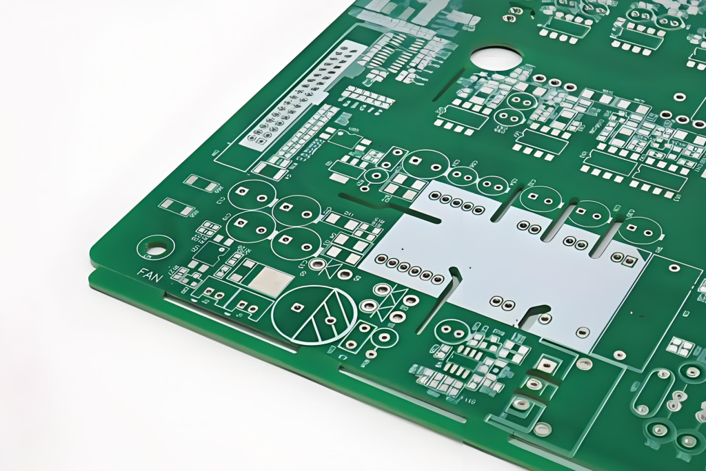
The Hidden Cause of Signal Integrity Failures
For 5G base stations, millimeter-wave radars, and AI acceleration cards, PCB signal integrity depends on two parameters: dielectric constant (Dk) and dissipation factor (Df). Many engineers simulate their designs with an ideal Dk of 3.5, only to find that finished products suffer over 10% impedance deviation.
The root cause rarely lies in the routing. More often, it’s neglected PCB lamination process control.
High-frequency lamination is precision process engineering — not simple thermal bonding. At Leyi Trading, we’ve spent 20 years mastering high-frequency PCB manufacturing. This article shares the five critical lamination control points that separate simulation from real-world performance.
Why Lamination Matters for High-Frequency PCBs
During lamination, heat and pressure bond the copper foil, prepreg, and core materials into a unified multilayer structure. For standard FR-4 boards, minor variations are tolerable. But for high-frequency materials like PTFE, Rogers, and hydrocarbon ceramics, even small process deviations cause:
- Dk drift → impedance mismatch → signal reflection
- Microbubbles → localized dielectric breakdown
- Resin flow inconsistency → uneven dielectric thickness → impedance variation across the board
- Substrate warpage → SMT placement errors → assembly defects
5 Critical Lamination Control Points
1. Pressure Ramp Rate Control (≤5–8 kg/cm²/min)
The rate at which pressure increases during lamination directly affects glass fiber alignment and resin distribution. If pressure ramps too quickly:
- Glass fibers slip, causing Dk drift
- Resin is pushed unevenly, creating thickness variations
- Inner-layer registration shifts, breaking fine-line connections
Our lamination presses are programmed to ramp pressure at a controlled ≤5–8 kg/cm²/min, with real-time monitoring to detect any deviation from the programmed curve.
2. Heating Rate and Staged Heat Preservation (1.5–2.5°C/min)
Temperature rise must be gradual and staged. We use a 1.5–2.5°C/min heating rate with staged heat preservation plateaus to:
- Allow resin to flow and wet out completely before gelation
- Eliminate microbubbles that would otherwise become trapped voids
- Ensure uniform cross-linking throughout the multilayer stack
Heating profiles are calibrated using DSC (Differential Scanning Calorimetry) data for each material system, ensuring the cure schedule matches the resin’s actual thermal behavior — not a generic textbook curve.
3. Segmented Pressing Pressure
Instead of applying a single high pressure throughout, we use segmented pressing — multiple pressure stages that correspond to different phases of resin flow and gelation:
- Stage 1 (Low pressure): allows initial resin flow and air evacuation
- Stage 2 (Medium pressure): promotes uniform resin distribution
- Stage 3 (High pressure): final compaction to achieve target dielectric thickness
This approach stabilizes dielectric thickness and reduces impedance offset by up to 40% compared to single-pressure lamination.
4. Gradient Cooling (≤3°C/min)
Cooling is just as critical as heating. Rapid cooling creates thermal stress that causes:
- Substrate warpage (especially in hybrid constructions like Rogers + FR-4)
- Inner-layer delamination
- Copper foil wrinkling
We control cooling at ≤3°C/min with gradient stages, allowing the multilayer structure to relax uniformly. This is especially important for rigid-flex PCBs and hybrid material constructions where different materials have different coefficients of thermal expansion.
5. High-Flatness Auxiliary Materials
The auxiliary materials used during lamination — separator plates, release films, and buffer pads — directly affect board flatness and surface quality. We use:
- Precision-ground steel separator plates (flatness ≤0.02mm)
- High-conductivity release films for uniform heat transfer
- Composite buffer pads that distribute pressure evenly
Poor auxiliary materials introduce test noise and surface defects that can mask real quality issues — or create false failures that waste production time.
First-Article Inspection: Closing the Loop
Every new lamination recipe undergoes mandatory first-article microscopic inspection before production approval. This includes:
- Cross-section microscopy to verify inter-layer bonding
- Dk measurement on test coupons
- Dimensional verification of dielectric thickness per layer
- Microvoid detection at 100x magnification
Complete process records — temperature curves, pressure logs, and material batch numbers — are retained for full traceability. This transparent lamination management is what narrows the gap between simulation and real-world PCB performance.
Material Expertise That Makes the Difference
Not all PCB manufacturers can handle high-frequency materials. Our factory has 20 years of specialized experience with:
- PTFE-based substrates (Taconic, Rogers RT/duroid)
- Hybrid constructions (Rogers + FR-4, PTFE + FR-4)
- Polyimide films for flexible and rigid-flex circuits
- Megtron 6 and other low-loss materials for 5G applications
Whether you need impedance-controlled boards for 5G infrastructure, radar systems for automotive ADAS, or high-speed digital boards for AI/ML applications, our lamination expertise ensures your design performs as simulated.
Get Your High-Frequency PCB Project Started
Don’t let lamination process gaps turn your simulation into a field failure. Get a quote within 24 hours for a DFM review of your high-frequency PCB design. Our engineering team will assess your stackup, material selection, and lamination requirements.
With ISO 9001 and IATF 16949 certifications, 1-40 layer capability, and 100,000 m² annual capacity, we’re equipped to handle your most demanding high-frequency PCB projects.