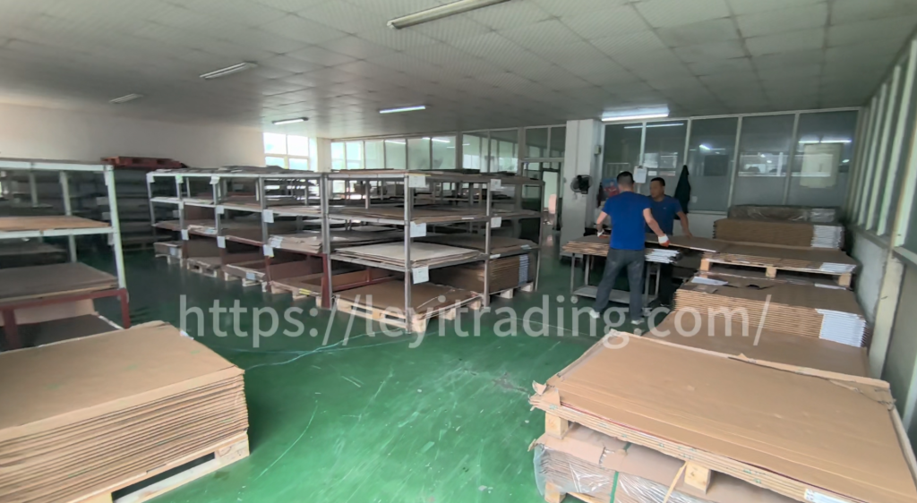
Why Incoming Quality Control (IQC) Determines PCBA Reliability
There’s a well-known principle in electronics manufacturing: a qualified PCBA is not assembled — it’s inspected. Industry data shows that over 60% of finished PCBA reliability depends on the quality of incoming materials. As the first and most critical checkpoint in the manufacturing process, Incoming Quality Control (IQC) prevents minor material defects from cascading into batch rework, field failures, and costly recalls.
At Leyi Trading, we operate a multi-layered IQC system that screens every incoming PCB bare board and component batch before it enters production. This article breaks down the core inspection points and why they matter for your project.
The IPC-600 Standard: The Baseline, Not the Ceiling
PCB bare board inspection follows the IPC-A-600 series international standards, which define acceptance criteria for printed circuit board quality. However, most professional manufacturers — including our factory — apply stricter internal control specifications that go beyond IPC requirements.
Why? Because IPC standards define the minimum acceptable quality. For high-reliability applications in aerospace, automotive, and 5G communications, “acceptable” simply isn’t good enough.
5 Core Inspection Dimensions of PCBA IQC
1. Substrate Thermal Parameter Verification
Before any board enters production, we sample and verify the substrate’s thermal parameters. This step eliminates a critical risk: false material labeling. If an FR-4 board is mislabeled as a high-Tg material, it will fail catastrophically during high-temperature reflow soldering.
Our lab verifies:
- Glass transition temperature (Tg)
- Coefficient of thermal expansion (CTE)
- Decomposition temperature (Td)
- Thermal stress resistance
2. Precision Dimensional Measurement
Board thickness, line width, and hole position tolerance are measured with precision instruments. Even a 0.05mm deviation in hole position can cause component misalignment during SMT placement, leading to solder defects and rework.
Key measurements include:
- Finished board thickness (±10% of nominal)
- Trace width and spacing (per design specification)
- Hole position accuracy (±0.075mm for standard, ±0.05mm for HDI)
- Panel size and warpage (≤0.75% for standard boards)
3. Dielectric Constant Testing for High-Frequency Boards
For RF and microwave PCBs, dielectric constant (Dk) directly determines impedance performance. We test Dk on every batch of high-frequency material to ensure signal integrity meets design requirements.
This is particularly critical for:
- 5G base station antennas
- Millimeter-wave radar systems
- High-speed digital boards (PCIe, DDR5)
4. Visual Inspection: Solder Mask and Surface Finish
Visual inspection focuses on defects that affect solderability and long-term reliability:
- Solder mask defects: bubbles, scratches, exposed copper
- Surface plating thickness: gold plating (ENIG), HASL, OSP — each has specific thickness requirements
- Gold brittleness detection: excessive gold thickness causes brittle solder joints
- Copper exposure on hole walls: indicates plating defects
5. Electrical Performance Testing
Electrical performance is the non-negotiable quality baseline. For high-reliability products, we conduct 100% full-circuit continuity testing on every board — not just sampling.
Testing methods include:
- Flying probe testing: for prototypes and low-volume (no fixture required)
- Fixture-based testing: for production volumes (fast, comprehensive)
- Characteristic impedance testing: using dedicated test coupons on high-frequency boards
- High-voltage insulation testing: verifies isolation between layers
Minor impedance deviations can be compensated by adjusting soldering parameters. However, batches with excessive deviations are immediately downgraded or scrapped — no exceptions.
The Closed-Loop Quality System
A mature IQC system doesn’t just inspect — it creates a closed-loop quality management mechanism. Inspection data flows back to optimize product design and manufacturing processes:
- Repeated substrate failures trigger supplier evaluation
- Plating thickness trends drive process parameter adjustments
- Impedance deviation patterns inform stackup design improvements
This data-driven approach balances quality with production efficiency, ensuring that every PCBA we deliver meets the reliability standards our customers expect.
Why IQC Matters for Your Project
Whether you’re sourcing PCB and PCBA services for consumer electronics, automotive systems, or industrial equipment, IQC is your first line of defense against field failures. By catching defects at the incoming stage, we prevent:
- Batch rework costs (typically 3-5x the cost of original assembly)
- Field failure and warranty claims
- Project delays caused by quality issues
- Reputation damage from defective products
Partner With a Manufacturer That Takes Quality Seriously
At Leyi Trading, our IQC process is just the beginning. With over 20 years of PCB manufacturing experience, ISO 9001 and IATF 16949 certifications, and a factory expanding to 3x capacity in 2026, we deliver the quality and reliability your projects demand.
Ready to discuss your PCB/PCBA project? Get a quote within 24 hours — our engineering team will review your design and provide DFM feedback at no cost.